Your location : Home > Solution > Plastic welding technique
Internal and external chamber welding process |
| Publisher: suzhou kailinneng automation equipment co., LTD Release time:2023-03-23 08:39:43 Click on the number of times:432 Shut down |
 |
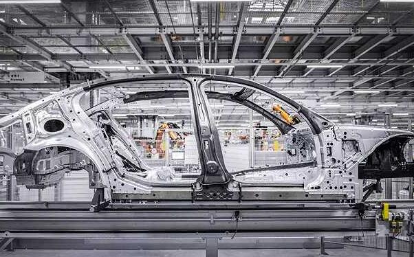
| Process analysis 2.1 Process line analysis Analyze the product process circuit according to the product data provided by the owner (if the owner only provides the sample car and sample parts, it needs to go through the process of sample car analysis → sample car disassembly → sample car measurement → sample car reassembly), and complete the design of the assembly and welding process circuit diagram or explosion diagram. 2.1.1 Product Segmentation The blocks of the same type of body are basically the same (general body is composed of floor, side circumference, front/rear circumference, door, top cover and other large assembly), but the connection mode and sequence of each assembly are often quite different. Only reasonable block can ensure the assembly and welding of the body. For example, the assembly sequence of the liberated flat cab is relatively special, forming the side and rear girth welding assembly first (left/right girth and rear girth forming welding assembly), and then forming the cab assembly. 2.1.2 Determine the baseline The design, manufacture and inspection of the whole body are built on the same coordinate system. In the body design, the reference (hole and surface) required in the process of assembly, welding, total assembly and handling is generally taken into account. The whole process of body assembly and welding must be built on a certain reference to ensure the geometric shape and size of the whole vehicle. At the same time, these benchmarks are also fixture design, manufacturing, adjustment, testing and maintenance benchmarks. The following aspects should be noted in determining the benchmark: a. Uniformity of datum, which is gradually transferred in the welding process; b. Datum should be easy to measure; c. The benchmark should ensure the accurate positioning of the parts; d. Reference shall be considered for ease of welding operation. 2.1.3 Determine the geometric accuracy of body assembly and the datum level of detection A geometric reference is an obvious part of a part or component, used to determine the theoretical position of the part within the X,Y,Z coordinate system; The accurate reference position of the component is used to ensure the accuracy of the geometric shape of the assembly, so the reference position is very important for the assembly work. Before studying the welding process, the reference position of the component needs to be carefully analyzed. The analysis of the geometric shape must be completed together with the user, and the reference position shall be determined by the user or determined by the designer before obtaining the consent of the user. In order to keep these benchmarks accurate, the following aspects must be strictly controlled in the process of fixture manufacturing and installation debugging. a. Adjust (test) the welding fixture during manufacturing; 
c. Test welding fixture during repair. 2.1.4 Determine the assembly sequence Each stamping part, sub-assembly and total parts of the body are assembled and welded in a strict sequence to complete the welding of the whole body. The assembly sequence of each part must ensure that all welding work can be completed and easy to weld. 2.1.5 Solder joint analysis It shows that the main parameters of the solder joint (solder joint number, location, amplitude, importance) is determined by the product design, but at present, some owners only provide product numerical model without product drawings. At this time, the main parameters of the solder joint need to be determined by the process designer. 2.1.5.1 Determination of shaped solder joints Reltively complex workpiece welding, often need to go through the assembly, repair welding process. In the assembly station, due to the production beat limitation, the number of equipment layout space needs and fixture effective space occupation and other reasons, it is impossible to complete all the welding work, but must complete part of the solder joints, these solder joints should be able to ensure that the workpiece left the fixture shape size, this part of the solder joints called shaped solder joints, in general, shaped solder joints account for about 1/3 of the total number of welding points. 2.1.5.2 Grouping Solder Joints There are many welding spots to be completed on each assembly of the body. The welding spots must be grouped in the preparation of the process, that is, the welding spots completed by a welding clamp in 1 working beat are divided into 1 welding spot group. 2.1.5.3 Preliminary selection of welding pliers After the welding joint group is completed, the selection of welding pliers can be carried out to determine the number of welding joint groups, namely the minimum number of welding pliers, according to the shape and size of the workpiece to determine the form of welding pliers (X shape,C shape) and throat depth, open gear, stroke, electrode shape, the hanging form of welding pliers (horizontal hanging, vertical hanging, rotating ring) according to the welding spot position and operation position. After the general fixture design is completed, the welding pliers model should be selected according to the spectrum provided by the selected welding pliers manufacturer. For the welding spot that cannot be found in the spectrum, the welding pliers need to be redesigned to match. 2.2 Prepare the process card Under the prerequisite conditions, after process analysis, you can begin to prepare the welding process card. The process card is a guiding document for the whole process of welding wire design, manufacturing and debugging, and is the basis for all the work of welding wire. The depth and quality of the process card are related to the design and manufacturing of welding wire. Debugging the whole process of quality and even success plays a decisive role. 2.2.1 Production beat General production time can be calculated according to Formula (1) : T day = annual working day x daily shift x working hours per shift xK1x In formula (1) of the program K2/ year, K1 is the working hour utilization rate, which is generally 0.9; K2 is the utilization rate of equipment, generally 0.8-0.9. 2..2 Station setting and production cycle of station Station is the basic unit of production line, and the production cycle of station must be less than or equal to the production line beat. The production cycle of the station is the whole process time from the loading of the parts to be welded to the completion of all the operations of the station and the removal of the workpiece. At the same time, the utilization rate of working hours and equipment should be considered. The production cycle of the station has a great relationship with the proficiency of the operator. Generally, the accurate production cycle of the station needs to be determined by the actual measurement. The process design should make the production cycle of all stations equal and close to the production beat as far as possible. 2.2.3 Working density Work density refers to the number of welding equipment and workers set on a station, which is mainly determined by the workpiece size, welding process and welding workload a. Determine the work density according to the workpiece size. The overall size is less than 1000 mmxl 500 mm, and the working density is 1; The overall size is less than 2 000 mmxl 500 mm, and the working density is 1-2; The overall size is less than 3 000 mmx 1500 mm, and the working density is 2-3; The overall dimension is less than 6 000 mmx 1 500 mm, and the working density is 3-4. b. Determine working density according to welding workload and production beat 2.2.4 Estimation of working hour quota Time quota = welding working time + auxiliary working time The time quota of each station or procedure is generally composed of the cumulative time of assembly, clamping, welding, loosening the fixture and sending the workpiece to the next station. It can also be obtained by enlarging the welding time, that is, the estimated quota, procedure time quota (working hours) = welding workload ÷ welding speed xK. The following is the general condition estimation of welding speed of several welding methods. The welding speed has a certain relationship with the spacing and distribution of welding joints and welds, the proximity of welding tongs and welding guns, and the difficulty of workers' operation, so it is only for the reference of process preparation. a. Spot welding with manual welding pliers 15 spots /min; b. Manipulator welding pliers spot welding 20 points /min; C.02 Semi-automatic welding 300mm /min; d. Manipulator C02 automatic welding 400 mm/min; e. Stud welding (manual 8 PCS /min; f. Convex welding nuts (manual) 3pcs /min; g. Copper brazing 100 mm/min. 2.2:5 Contents of the process card a. The general diagram of the weldment (assembly or assembly) is the axonometric diagram (stereogram). In the diagram, the name, drawing number and quantity of the stamping parts entering the assembly shall be marked; At the same time to mark the position of the welding spot, the number, and even the welding sequence; Position, quantity and welding method of various standard parts such as nuts, studs and supports. b. II Process description: The whole process of loading, positioning and clamping, welding and sending the workpiece to the next procedure after welding is described in a simple and comprehensive way. c. Make qualitative and quantitative analysis of the names, numbers and quantities of fixtures, equipment, accessories and tools used in the process. d. Give the time quota of the process, or even give it by each working step, and the working time can be determined by the following methods: by experience; Artificial imitation, stopwatch measurement; Computer simulation. |
|
|
 Mobile web site!
